
Opening the framework — why this matters
Think of this as a checklist an energy engineer would actually use when you need a utility-scale battery that doesn’t just look good on paper. The goal: specify systems that hit your performance targets while avoiding thermal headaches and unexpected losses. If you’re curious how that compares to smaller installs, consider the same principles that guide a home energy storage system—though scaled-up systems need different thermal management and controls. Smaller-scale users, like households with home battery backup systems, care about reliability and cycle life just as much, but the risk profile is different when megawatt-hours are on the line.
Framework overview: four layers to specify
Use four decision layers to keep specs consistent and testable: performance envelope, cell and pack selection, thermal and safety systems, and operational controls. Each layer answers a specific question and produces measurable requirements you can contract against.
– Performance envelope: target RTE (round-trip efficiency), usable capacity, and power rating. – Cell and pack selection: chemistry, C-rate, and expected degradation. – Thermal & safety: cooling approach, thermal runaway mitigation, and fire suppression design. – Controls & commissioning: BMS behavior, SoC management, and acceptance testing.
Layer 1 — Define the performance envelope in measurable terms
Start with numbers: required round-trip efficiency (RTE), minimum usable energy (MWh), peak discharge power (MW), and acceptable depth-of-discharge (DoD). Put these in the RFP. Don’t just say “high efficiency” — specify a target RTE and the conditions under which it’s measured (ambient temperature, C-rate, SoC window). That clarity prevents vendors from quoting optimistic lab numbers that collapse under real-world duty cycles.
Layer 2 — Choose cells and packs with deployment in mind
Select chemistry for the expected duty: high-C-rate applications might favor LFP for thermal stability, while lithium-nickel chemistries can work where energy density dominates. Ask for validated cycle-life curves under the same SoC and C-rate profiles you plan to use. Include BMS requirements for cell balancing, fault detection, and firmware update paths — these help manage long-term degradation and protect against thermal runaway.
Layer 3 — Thermal management isn’t optional
Cooling strategy drives real-world performance. Passive systems may reduce maintenance but can’t always sustain power at high ambient temps; active liquid cooling buys headroom but adds complexity and leak risk. Specify maximum cell temperature under worst-case discharge and charge profiles, plus system response time for thermal events. Also mandate thermal imaging or fiber-optic temperature sensors during commissioning — they catch hot spots that bulk thermistors miss. —
Layer 4 — Operational controls and acceptance testing
Define how the system will operate day-to-day: SoC windows, charge/discharge ramp rates, round-trip efficiency baselines, and islanding behavior. Require acceptance testing with real power hardware-in-the-loop where possible: run a sequence of cycles at target C-rates, measure RTE across the SoC band, and force thermal stress tests. Include firmware version locks for commissioning and procedures for re-certification after major updates.
Common mistakes I see in specs — and how to dodge them
Teams often make three related errors: vague efficiency claims, under-specified thermal margins, and hand-wavy acceptance tests. Vague claims let vendors quote lab RTE numbers measured at a single C-rate and 25°C — but your grid service might ask for high-power dispatch at 40°C. Likewise, insufficient thermal margins mean a unit that works fine most days but trips during heat waves — and we all remember how the February 2021 Texas winter storm exposed weaknesses in many power systems. The fix: lock specs to operating envelopes and require on-site validation under realistic conditions.
A short case example — specifying for peak-shaving in a hot climate
Say the project is peak-shaving in Phoenix: you need fast discharge at high ambient temps. That means selecting cells with proven high-temp performance, specifying liquid cooling or robust air conditioning, and writing acceptance tests that include sustained discharges at 50°C ambient. Demand vendors show historical test data or third-party lab reports — and require a plan for thermal runaway containment. Real deployments in hot regions have shown that upfront investment in cooling saves replacements and outages later.
Testing protocols and contract language that protect you
Put the important tests in the contract: cycle testing at project C-rate, RTE measurement method and tolerances, thermal stress test pass/fail criteria, and First Article Inspection with your commissioning team present. Include clauses for firmware freeze during acceptance and defined remedies if measured performance deviates beyond agreed tolerances. These terms keep procurement and engineering aligned.
Practical checklist before signing off
– Does the quoted RTE include inverter and auxiliary losses at the planned C-rate? – Is there a defined thermal management strategy with worst-case temperatures and response times? – Are BMS features (cell balancing, fault logging, remote updates) contractually required? – Are acceptance tests specified, witnessed, and tied to payment milestones?
Advisory: three golden metrics to use as your final litmus test
1) Net project RTE over the mission profile: measured across your actual SoC window and C-rate, not a single lab condition. 2) Thermal margin: maximum cell temperature under worst-case dispatch plus documented containment/mitigation measures. 3) Proven degradation curve: cycle life at your target DoD and C-rate with third-party or vendor-validated data.
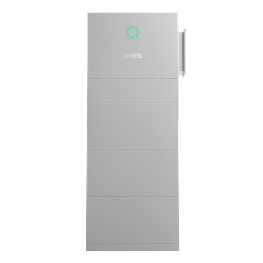
WHES brings practical system design and commissioning experience to those exact metrics and helps translate engineering specs into reliable field outcomes.