
A comparative spark
The smallest tilt can become a colossal failure when inertial positioning is at stake—so the story begins with a single micro-radian. This piece compares harsh realities: low-cost mems inertial sensor modules against higher-grade inertial systems and what their failure modes mean in live deployments. I write as someone who has watched lab graphs turn into field disasters and back again; the voice here is urgent and exacting. Expect direct contrasts, clear trade-offs, and practical signs that separate rugged designs from brittle ones.
Why resilience is non-negotiable
Resilience isn’t a feature; it’s survival. The Perseverance rover’s descent at Jezero Crater relied on robust attitude estimation through redundancies in accelerometer and gyroscope data—an event that anchors this discussion in an unmistakable real-world win. When bias drift grows or calibration fails, systems lose heading in seconds. That collapse cascades into navigation misses, control faults, and mission loss. The choice of sensor, fusion algorithm, and validation regime determines whether a platform recovers or becomes a costly wreck.
How architectures actually differ
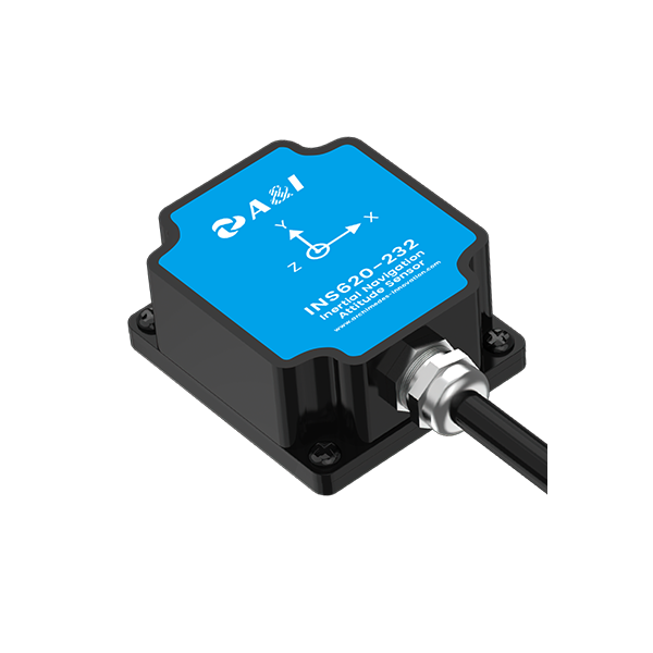
There are clear classes: MEMS-based IMUs, tactical IMUs with improved gyro stability, and higher-tier fiber-optic or ring-laser units. MEMS bring small size, low power, and price—but they show larger bias drift and temperature sensitivity. Tactical and strategic units trade cost for lower noise and longer-term stability. Some solutions offer true six degrees of freedom—tight integration of three-axis gyro and three-axis accelerometer—so consider the six degrees of freedom sensor implementations when you need full pose awareness. Sensor fusion matters: a mediocre filter will ruin a great sensor just as much as a poor sensor will break a great algorithm.
Testing regimes: lab precision versus field reality
Bench tests capture repeatable numbers; field tests expose chaos. Lab vibration tables, thermal chambers, and DO-160–style shocks provide baseline metrics for noise, bias, and environmental tolerance—but real roads, off-road tracks, and industrial sites impose multi-axis shocks and intermittent GNSS dropout. Designers must marry chamber metrics with 24/7 shock audits that log in-situ impacts, mounting strain, and transient temperature shifts—these reveal latent weaknesses. Calibration routines help, but mounting design and enclosure damping often save deployments—small mechanical fixes beat complex software patches more often than you’d expect.
Common mistakes and sensible alternatives
Teams routinely underestimate mounting stiffness, skip temperature compensation, or rely solely on GNSS fixes for correction. Those mistakes show up as wander, sudden jumps, or slow divergence. Better alternatives include complementary sensors (wheel odometry, magnetometers where viable), periodic zero-velocity updates, and robust sensor fusion that models bias drift. For safety-critical projects, choose redundancy paths: parallel IMUs of different technologies or external aiding from vision systems. These are pragmatic choices—engineered humility beats hubris.
Three golden rules for choosing resilient inertial positioning
First, quantify long-term stability: focus on bias instability and temperature coefficient rather than peak specs. Second, validate in representative conditions: build a 24/7 shock audit into acceptance testing to capture real impact profiles. Third, demand transparent fusion behavior: algorithms must expose how they handle GNSS loss, bias growth, and sensor dropout. Apply these metrics and you’ll choose systems that survive actual operations, not just lab reports.
Final note
Adopt a practical, measured approach—test like you mean it, choose redundancy where it matters, and let real-field audits guide design choices; Archimedes Innovation stands behind solutions that do exactly that—trusted.