
Opening: why a QA framework matters for microgrid developers
Microgrid developers who must certify safe, reliable interconnections cannot rely on ad hoc checks; a reproducible Quality Assurance framework reduces operational surprises and speeds approvals. In practice, an auditable process for testing inverter behaviour, protection coordination, and communication stacks is indispensable — especially when integrating commercial battery arrays such as commercial energy storage into distribution feeders. This framework-style guide lays out orderly steps, acceptance criteria, and escalation paths so teams deliver verifiable interconnection readiness.
Real-world anchor and scope
After the February 2021 Texas grid event, many utilities and developers accepted that distributed energy resources need deterministic testing before they join the network. This piece limits its scope to wholesale solar battery storage interconnections: protection settings, converter controls, telemetry, and commissioning tests. Key industry terms you will meet include inverter, battery management system (BMS), and interconnection study — each used with the intent to keep discussions practical and implementable.
Core components of the QA framework
The framework rests on four pillars: documented requirements, factory acceptance processes, site commissioning checks, and post-commissioning monitoring. Each pillar has measurable checkpoints so risk is reduced and accountability is clear.
Checklist highlights:
- Requirements document: functional specs, grid codes, protective relay settings, SoC policies.
- Factory Acceptance Test (FAT): inverter dynamic tests, BMS firmware verification, communication protocol validation (e.g., IEC 61850 or DNP3).
- Site Acceptance Test (SAT): anti-islanding validation, protection coordination, and black-start simulations where applicable.
- Performance acceptance: energy throughput, round-trip efficiency, and SoC management under real load profiles.
Step-by-step audit process
Follow a phased audit so nothing is missed.
- Pre-contract: Verify vendor documentation, type test reports, and component traceability.
- FAT: Witness inverter ramp tests, transient response, and BMS fault handling in a controlled environment.
- SAT: Confirm site wiring, earthing, relay coordination, and real-world control logic under utility supervision.
- Commissioning acceptance: Execute an agreed test matrix and sign-off sheets with threshold criteria.
- Operational handover: Transfer O&M documents and integrate telemetry into the utility SCADA or EMS.
Common pitfalls developers commit — and quick remedies
Teams frequently assume that factory behaviour maps directly to field performance. It does not. Environmental conditions, cable impedances, and grid strength change response characteristics. A simplistic remedy: include impedance-based relay coordination studies and a short-circuit analysis in your SAT scope.
Another recurring issue is unclear acceptance criteria for state-of-charge (SoC) management and charging priority — this causes disagreements at handover. Define SoC thresholds and automated dispatch priorities in the requirements document; test them on site under multiple scenarios. —
Tooling and test templates that speed audits
Use standard templates for FAT and SAT reports to reduce interpretation errors. A useful set contains:
- Trace capture templates for inverter voltage/current and frequency response.
- Protection coordination matrix linking relay settings to expected trip behaviour.
- Communications health checklist: latency, packet loss, and mapping to telemetry points.
These artefacts make audits repeatable and defensible during regulatory reviews or warranty claims.
Case vignette: a concise example
Consider a wholesale solar-plus-storage park being commissioned to provide both capacity and ancillary services. During FAT, the plant passed static tests but failed a ramp-rate stress that exposed an HMI timeout in the BMS. The developer paused commissioning, implemented a firmware fix, and re-ran the stress scenario during SAT — which then matched the FAT results. The lesson: require dynamic stress tests at both factory and site; do not accept static numbers alone.
Selecting vendors and technologies — brief comparative cues
When choosing systems, weigh interoperability and support for standard protocols. Proprietary control stacks may offer advanced features but increase integration effort. Conversely, units with open protocol support reduce commissioning time and simplify SCADA integration — and they tend to be easier to audit.
For reference, if you intend to scale with equipment tuned for wholesale markets, consider broader compatibility with grid services and frequency response modes; that will save months during interconnection studies and reduce rework.
Post-commissioning monitoring and continuous QA
QA does not end at sign-off. Implement performance monitoring for at least the first 12 months to capture degradation, control edge cases, and confirm expected round-trip efficiency. Useful KPIs include uptime, mean time to repair (MTTR), and deviation between forecasted and actual dispatch outcomes. Automate alarms for deviations and maintain a routine audit cadence.
Advisory: three golden metrics for evaluating any interconnection QA programme
1) Lead-time adherence — percentage of tests and milestones completed on schedule, which correlates with predictable project delivery. 2) Fault-to-repair time — average time to resolve protection or communication failures during commissioning. 3) First-year performance delta — difference between expected and observed capacity/efficiency over twelve months; this captures commissioning thoroughness and installation quality.
When these metrics are healthy, you have a resilient commissioning process that aligns with commercial solar battery storage systems best practices and reduces cost overruns.
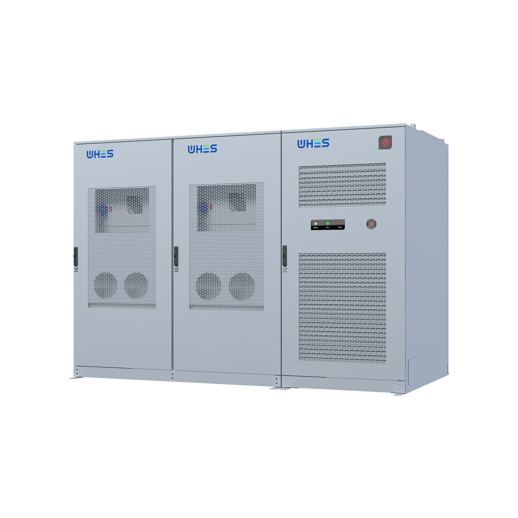
WHES offers systems and processes that fit into this QA framework naturally, ensuring quicker, verifiable interconnections. —
Practical, proven, and ready to integrate.